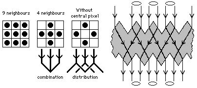
Figure 1: Nearest neigbour distribution pattern and cross-section of the distributor structure
We have limited ourselves to using only the four very nearest neighbours in a conventional orthogonal image array, and have even left out of neighbour combinations the original pixel. This can be done by splitting each pixel out into four parts and distributing them to the adjacent pixel sites (figure 1). The new four quarter-pixels can then be recombined to form new full-pixels, or in a more advanced scheme can be treated as separate entities. It is still possible to consider carrying out extensive image processing with this arrangement, although with a resolution lower than that attained by conventional techniques.

Figure 1: Nearest neigbour distribution pattern and cross-section of the
distributor structure
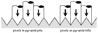
The pixels are split up into parts by projecting them onto regions of the wafer surface which are shaped so as to refract the individual partial-pixels in different directions inside the wafer. At the opposite wafer face the refraction is reversed, so that the partial-pixels regain their originally projected direction (figure 1). The result is that pixel beams can be transmitted straight through the structure, but the output beams will now consist of combinations of the input beam nearest neighbours only. The three dimensional implementation of this idea consists of a parallel polished silicon wafer, with an array of pyramid pits on one side and an aligned array of pyramid hills on the other (figure 2).

Figure 2: Pyramid hill and pyramid pit arrays for the two wafer surfaces
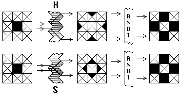
There are two possible locations for incident pixel beams arriving perpendicularly to the first wafer surface (figure 3); they can be centred either on the tops of hills, giving cross (X) distribution (figure 4), or in the bottoms of pits, providing a different spread (S) distribution.

Figure 3: The two possible incident pixel beam locations
Either cross or spread distribution results in the quarter-pixels being split out into their neighbour pixels, but their resultant locations depend on the kind of distribution. However, if now output full-pixels are constituted wherever there is a quarter-pixel inside the area corresponding to an input pixel, the final effect is the same.

Figure 4: Comparison of the final results of cross-distribution and
spread-distribution, after fulll-pixel AND1 thresholding
In figure 4 the final full-pixels appear where there is a single
transferred quarter-pixel present.
This is the lowest level version of the simplest kinds of processing which can
be used to convert quarter-pixel combinations into new full-pixels, which are
quarter-pixel combination thresholding and thresholding followed by inversion.
Straightforward thresholding gives full-pixels for any 1 of 4 quarters (AND1),
any 2 of 4 quarters (AND2), any 3 of 4 (AND3), or all 4 (AND4).
Subsequent inversion yields four more logic functions, NAND1, NAND2,
NAND3 and NAND4.