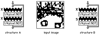
Figure 5: Schematic representation of a processing sequence, and the initial image
The possible combinations of the different distributions, the different logic functions, and the possibility of a re-cycling or looping operation which will pass the image repeatedly through the same set of silicon and logic planes result in a range of interesting non-programmed processes. We have carried out a number of simulations using different processing-component combinations to evaluate the usefulness of structures based on these ideas. The component arrangement is shown as on the left of the figure 5, the initial image is put in once, and the subsequent operation sequence is indicated. For most of the following examples we have used the initial pixeled image shown in figure 5, or a part of it where it is useful to show more detail.

Figure 5: Schematic representation of a processing sequence, and the initial
image
Cross or spread pixel distribution plus full-pixel thresholding gives a threshold-controllable degree of noise or detail removal depending on whether AND1, AND2, AND3 or AND4 is used (figure 6). Thresholding with AND2 gives a result similar to conventional single-pixel-noise removal, with some exceptions in detail but with both black and white pixels treated equally.

Figure 6: Detail removal: cross or spread distribution followed by AND1, AND2,
AND3 or AND4
If the intention is to use structures of this type in a looping or circulatory processing scheme (as for example in an architecture related to the optical CLIP [1]) then a first requirement is for circulatory stability: going round the loop should not result in lateral dispersion of initially present detail. A logic-less loop which unfortunately exhibits such a dispersion is the combination of two successive X or S distributors, each followed by quarter-pixel inversion (structure A in figure 7). The problem is solved by changing one of the distributors, to give X-then-S or S-then-X with quarter-pixel inversions (structure B in figure 7).

Figure 7: Loop processing stability: unstable (structure A) and stable
(structure B) configurations
The first image shown in each of figures 8 and 9 is the first intermediate one, after just one X distribution and a quarter-pixel inversion. Structure A (figure 8) shows detail dispersion which increases with the number of circulatory passes.

Figure 8: Detail dispersion exhibited by structure A
Although the first intermediate image of structure B (figure 9) is the same as that of structure A, the loop now gives a stable resulting image; the S distribution inverts the initial X distribution exactly.

Figure 9: Detail stability exhibited by structure B
Adding in full-pixel NAND1 thresholding instead of quarter-pixel inversion removes the necessity for two kinds of distributor, and the sequence of X_NAND1_X_NAND1 in a loop provides a stable image after one stage of single-pixel noise reduction (figure 10), as does S_NAND1_S_NAND1.

Figure 10: A stable loop configuration with two similar distributors
The simplest stable or do-nothing loop consists of just a pair of opposite distributors, X-then-S (figure 11) or S-then-X.

Figure 11: The simplest stable loop configuration
This provides the basis for a possible stable circulatory processing scheme, where the pixels are first distributed, operated on by a controllable logic plane inserted between the two distributors, and then re-distributed back to their own original pixel locations.
The four-fold split-up of the original image pixels means that not only individual quarter-pixels but quarter-pixel copies of the complete image are projected in the four directions of the image plane. After a number of passes, four full-pixel images the same as the single original one may be restored by reading the distributor output through an AND1 plane (figure 12). It should be noticed that the four images cross each other in the plane without mutual interference; each is confined to its own characteristic quarter-pixel at every stage.

Figure 12: Four-fold split-up of a single image to give four copies of the
original
Conversely, a single image may be constructed out of four spatially separated different parts by projection of their quarter-pixel images into a central region and subjecting the resultant combination to an AND2 operation (figure 13).

Figure 13: Combination of four separate image-parts to give a single image